Slickline refers to a single strand wire which is used to run tools into wellbore for several purposes. It is used in the oil and gas industry, but also describes that niche of the industry that involves using a slickline truck or doing a slickline job.
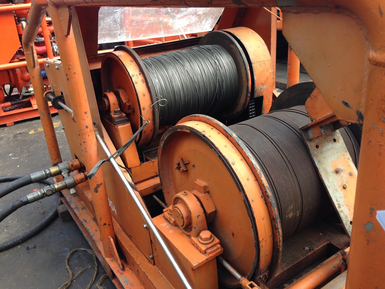
Slickline looks like a long, smooth, unbraided wire, often shiny, silver/chrome in appearance. It comes in varying lengths, according to the depth of wells in the area it is used (it can be ordered to specification) up to 35,000 feet in length. It is used to lower and raise downhole tools used in oil and gas well maintenance to the appropriate depth of the drilled well. In use and appearance it is connected by the drum it is spooled off of in the back of the slickline truck to the wireline sheave a round wheel grooved and sized to accept a specified line and positioned to redirect the line to another sheave that will allow the slickline to enter the wellbore.[1] Slickline is used to lower downhole tools into an oil or gas well to perform a specified maintenance job downhole. Downhole refers to the area in the pipe below surface, the pipe being either the casing cemented in the hole by the drilling rig (which keeps the drilled hole from caving in and pressure from the various oil or gas zones downhole from feeding into one another) or the tubing, a smaller diameter pipe hung inside the casing.

Slickline is more commonly used in production tubing. The wireline operator monitors at surface the slickline tension via a weight indicator gauge and the depth via a depth counter 'zeroed' from surface, lowers the downhole tool to the proper depth, completes the job by manipulating the downhole tool mechanically, checks to make sure it worked if possible, and pulls the tool back out by winding the slickline back onto the drum it was spooled from. The slickline drum is controlled by a hydraulic pump, which in turn is controlled by the 'slickline operator'.
Slickline comes in different sizes and grades. The larger the size, and higher the grade, generally means the higher line tension can be pulled before the line snaps at the weakest spot and causes a costly 'fishing' job. Due to downhole tools getting stuck because of malfunctions or 'downhole conditions' including sand, scale, salt, asphaltenes, and other well byproducts settling or loosening off the pipe walls because of agitation either by the downhole tools or a change in downhole inflow, sometimes it is necessary to pull hard on the tools to bring them back uphole to surface. If the tools are stuck, and the operator pulls too hard, the line will snap or pull apart at the weakest spot, which is generally closer to surface as the further uphole the weak point in the line is, the more weight it has to support (the weight of the line).
Weak spots in the line can be caused by making the circle around the counter wheel, making a bend around a sheave, a kink in a line from normal use (when rigging up the equipment extra line must be pulled out from the truck to give enough slack when the pressure control lubricator is picked up - this leaves line coiled on the often rutted ground, and sometimes it snags and kinks the line).
When the slickline parts, this can create an expensive 'fishing' job. It is called fishing because you often have to try different 'fishing' tools until you get a 'bite', then you have to work the original tools downhole free, or cut off the slickline where they join the tools downhole so that you can pull the broken slickline back to surface and out of the way, in order to fish the stuck toolstring. Because of the downtime involved in 'fishing', meaning not being able to flow the oil/gas well, the client is losing money by lack of production and also the cost of the slickline unit to fish, and the cost of what is left in the hole if it is not fished out (in the oil/gas industry, if the cause of the fishing job was not the fault of the slickline company, the oil/gas company is usually responsible to pay for it, and it can be very expensive).
Slickline was originally called measuring line, because the line was flat like a tape measure, and marked with depth increments so the operators would know how deep in the hole they were. This probably changed because the flat measuring line wasn't as strong as the modern slickline, and separate depth counters were developed. It is advantageous to keep the diameter of the wire as small as possible for the following reasons:
The sizes of solid wireline in most common uses are: 0.092", 0.108", 0.125", 0.140", 0.150", and 0.160" in diameter, and are obtainable from the wire-drawing mills in one-piece standard lengths of 18,000, 20,000, 25,000 and 30,000 foot lengths. Other diameters and lengths are usually available on request from the suppliers, with the largest size currently available at 0.188".
Mechanical jars look like a long, tubular piece of machined metal that slides longer or shorter approximately 75% to 90% of its total length. They give the effect of hammering on the downhole tools. The weight or hit of the 'hammer' depends on how much sinker bar is added above the jars. Generally, a slickline operator controls the downhole tools with taps and hits from the sinker bar via the mechanical jars, controlled at surface by lowering or raising the toolstring and monitoring weight, depth, and pressure. Mechanical jars for slickline can hit up or down the hole, making them a versatile form of jarring.
Hydraulic jars for slickline are generally meant to jar up only, because not enough sinker bar is able to feasibly be lubricated in to jar down on the downhole tools. Hydraulic jars work by the operator pulling up on the line, which puts an upward force on the top of the hydraulic jars. The bottom of the hydraulic jars is usually attached by threaded connection to the mechanical jars, which are attached to the downhole tools. Depending on how hard the operator pulls on the hydraulic jars will affect how fast they hit, and how hard they hit. When the top is pulled on, the inner mandrel begins to slide upwards. It has a restriction in it that hydraulic fluid has to bypass as it is pulled upwards, until it reaches an area of no restriction, allowing it to slide rapidly. The reason for the initial tighter restriction is to allow the operator to pull his line to the desired hitting range.
Generally once he hits that range on his weight indicator, he waits while the jars open to the less restricted point, whereupon the sinker bar travels upwards rapidly, providing an upwards hit on the downhole tools. The jars can then be 'reset' by lowering the line until the weight of the sinker bar closes, or pushes the inner mandrel of the hydraulic jars back to the starting position. Because the hydraulic jars are designed to provide a wait time to allow the operator to get up to the desired line tension, they can provide a very effective upwards hit.
Mechanical jar and hydraulic jar hitting power is affected by the length of the jars (the longer the length, they faster they can travel before they stop), the mass of the weight above them (the more the mass, the harder they will hit), and the tension of the line pulling on them.
Some completion components may be deployed and retrieved on slickline such as wireline retrievable safety valves, battery powered downhole gauges, perforating, placing explosively set bridge plugs, and placing or retrieving gas lift valves. Slickline can also be used for fishing, the process of trying to retrieve other equipment and wire, which has been dropped down the hole.

Source : Wikipedia
Slickline looks like a long, smooth, unbraided wire, often shiny, silver/chrome in appearance. It comes in varying lengths, according to the depth of wells in the area it is used (it can be ordered to specification) up to 35,000 feet in length. It is used to lower and raise downhole tools used in oil and gas well maintenance to the appropriate depth of the drilled well. In use and appearance it is connected by the drum it is spooled off of in the back of the slickline truck to the wireline sheave a round wheel grooved and sized to accept a specified line and positioned to redirect the line to another sheave that will allow the slickline to enter the wellbore.[1] Slickline is used to lower downhole tools into an oil or gas well to perform a specified maintenance job downhole. Downhole refers to the area in the pipe below surface, the pipe being either the casing cemented in the hole by the drilling rig (which keeps the drilled hole from caving in and pressure from the various oil or gas zones downhole from feeding into one another) or the tubing, a smaller diameter pipe hung inside the casing.
Slickline is more commonly used in production tubing. The wireline operator monitors at surface the slickline tension via a weight indicator gauge and the depth via a depth counter 'zeroed' from surface, lowers the downhole tool to the proper depth, completes the job by manipulating the downhole tool mechanically, checks to make sure it worked if possible, and pulls the tool back out by winding the slickline back onto the drum it was spooled from. The slickline drum is controlled by a hydraulic pump, which in turn is controlled by the 'slickline operator'.
Slickline comes in different sizes and grades. The larger the size, and higher the grade, generally means the higher line tension can be pulled before the line snaps at the weakest spot and causes a costly 'fishing' job. Due to downhole tools getting stuck because of malfunctions or 'downhole conditions' including sand, scale, salt, asphaltenes, and other well byproducts settling or loosening off the pipe walls because of agitation either by the downhole tools or a change in downhole inflow, sometimes it is necessary to pull hard on the tools to bring them back uphole to surface. If the tools are stuck, and the operator pulls too hard, the line will snap or pull apart at the weakest spot, which is generally closer to surface as the further uphole the weak point in the line is, the more weight it has to support (the weight of the line).
Weak spots in the line can be caused by making the circle around the counter wheel, making a bend around a sheave, a kink in a line from normal use (when rigging up the equipment extra line must be pulled out from the truck to give enough slack when the pressure control lubricator is picked up - this leaves line coiled on the often rutted ground, and sometimes it snags and kinks the line).
When the slickline parts, this can create an expensive 'fishing' job. It is called fishing because you often have to try different 'fishing' tools until you get a 'bite', then you have to work the original tools downhole free, or cut off the slickline where they join the tools downhole so that you can pull the broken slickline back to surface and out of the way, in order to fish the stuck toolstring. Because of the downtime involved in 'fishing', meaning not being able to flow the oil/gas well, the client is losing money by lack of production and also the cost of the slickline unit to fish, and the cost of what is left in the hole if it is not fished out (in the oil/gas industry, if the cause of the fishing job was not the fault of the slickline company, the oil/gas company is usually responsible to pay for it, and it can be very expensive).
Slickline was originally called measuring line, because the line was flat like a tape measure, and marked with depth increments so the operators would know how deep in the hole they were. This probably changed because the flat measuring line wasn't as strong as the modern slickline, and separate depth counters were developed. It is advantageous to keep the diameter of the wire as small as possible for the following reasons:
- It reduces the load of its own weight.
- It can be run over smaller diameter sheaves, and wound on smaller diameter spools or reels without overstressing by bending (where the wire bends makes it weaker. Where it makes a complete circle, such as a counter wheel, makes it weaker yet).
- It keeps the reel drum size to a minimum (which reduces the area needed in the back of the slickline unit to house the drum and hydraulic pump, reducing weight and leaving more room for the other specialized equipment needed for slickline operations).
- It provides a small cross-section area for operation under pressure.
The sizes of solid wireline in most common uses are: 0.092", 0.108", 0.125", 0.140", 0.150", and 0.160" in diameter, and are obtainable from the wire-drawing mills in one-piece standard lengths of 18,000, 20,000, 25,000 and 30,000 foot lengths. Other diameters and lengths are usually available on request from the suppliers, with the largest size currently available at 0.188".
Mechanical and Hydraulic Jars
Slickline tools operate with a mechanical action, controlled from surface in the wireline trucks operators compartment. Typically, this mechanical action is accomplished by the operation of jars. There are generally two types of jars; mechanical and hydraulic.Mechanical jars look like a long, tubular piece of machined metal that slides longer or shorter approximately 75% to 90% of its total length. They give the effect of hammering on the downhole tools. The weight or hit of the 'hammer' depends on how much sinker bar is added above the jars. Generally, a slickline operator controls the downhole tools with taps and hits from the sinker bar via the mechanical jars, controlled at surface by lowering or raising the toolstring and monitoring weight, depth, and pressure. Mechanical jars for slickline can hit up or down the hole, making them a versatile form of jarring.
Hydraulic jars for slickline are generally meant to jar up only, because not enough sinker bar is able to feasibly be lubricated in to jar down on the downhole tools. Hydraulic jars work by the operator pulling up on the line, which puts an upward force on the top of the hydraulic jars. The bottom of the hydraulic jars is usually attached by threaded connection to the mechanical jars, which are attached to the downhole tools. Depending on how hard the operator pulls on the hydraulic jars will affect how fast they hit, and how hard they hit. When the top is pulled on, the inner mandrel begins to slide upwards. It has a restriction in it that hydraulic fluid has to bypass as it is pulled upwards, until it reaches an area of no restriction, allowing it to slide rapidly. The reason for the initial tighter restriction is to allow the operator to pull his line to the desired hitting range.
Generally once he hits that range on his weight indicator, he waits while the jars open to the less restricted point, whereupon the sinker bar travels upwards rapidly, providing an upwards hit on the downhole tools. The jars can then be 'reset' by lowering the line until the weight of the sinker bar closes, or pushes the inner mandrel of the hydraulic jars back to the starting position. Because the hydraulic jars are designed to provide a wait time to allow the operator to get up to the desired line tension, they can provide a very effective upwards hit.
Mechanical jar and hydraulic jar hitting power is affected by the length of the jars (the longer the length, they faster they can travel before they stop), the mass of the weight above them (the more the mass, the harder they will hit), and the tension of the line pulling on them.
Some completion components may be deployed and retrieved on slickline such as wireline retrievable safety valves, battery powered downhole gauges, perforating, placing explosively set bridge plugs, and placing or retrieving gas lift valves. Slickline can also be used for fishing, the process of trying to retrieve other equipment and wire, which has been dropped down the hole.
Applications
The most common applications for slickline are:- Tagging T.D. (Total Depth, which is the furthest depth possible down the wellbore)
- Gauge Ring runs (which is running a special sized downhole tool called a gauge ring, which comes in various pre-machined diameters, designed to ensure the pipe is clear to a certain point)
- Tubing Broach / Plunger Installations (a tubing broach looks like an aggressive, tubular file, available in different diameters, used for removing burrs and crimps in the inside of tubing and casing in oil and gas wells)
- Bailing sand and debris (removing formation sand/rock and other such debris left over from the drilling and completion of the well, using a specialized tool called a bailer. This tool uses either a Chinese water pump type stroke action or a hydrostatic vacuum action to suction up the downhole debris, allowing it to be conveyed back to surface via the wireline)
- Shifting sleeves (formations downhole can be isolated behind sliding metal 'windows' called sliding sleeves. They are shifted open or closed by means of a specialized shifting tool locating the sleeve and it being jarred up or down, providing access or closing off that formation or section of casing)
- Setting / Pulling plugs and chokes (specialized downhole tools which either lock into pre-machined restrictions in the tubing, or which lock into the tubing itself, sealing pressure from below or above the plug)
- Setting / Pulling gas lift valves
- Running tailpipes (tubing extensions where the tubing is not landed close enough to the formation perforations in the casing)
- Bottom hole pressure and temperature surveys (specialized electronic and mechanical tools designed to measure the pressure and temperature at predetermined depths in the wellbore. This data can be used to determine reservoir life)
- Spinner Surveys (to determine which formation perforations have the best inflow / which perforations make the most water / liquids)
- Kinley perforator, sandline cutter, and caliper
- Running production logging tools
- Fishing operations (fishing usually refers to attempting to retrieve lost tools or wire, or other debris that was not intended to restrict the flow / disrupt the well operations. Fishing can be difficult, due the fish being downhole, and other affecting conditions such as high pressure, the fish being jammed in the tubing / casing)
- Paraffin cutting (making a hole through and removing a wax buildup, which is a byproduct of oil cooling too much to reach surface)
- Chipping ice / salt (restrictions and plugs which can be formed as by products of a flowing well)
- Lubricating long assemblies in and out of the hole (lubricating is done via a larger than tool overall diameter pipe, joined at surface on top of the wellhead, which houses the valve that shuts the pressure in downhole. The lubricator should be long enough to be able to swallow the toolstring and downhole tools that are to be run or pulled)

Braided line
Braided line is generally used when the strength of slickline is insufficient for the task. Most commonly, this is for heavy fishing such as retrieving broken drill pipe. The most common use for braided line is fishing electric line tools.Slickline Tools
Jar
This type of tool can be extended and closed rapidly to induce a mechanical shock to the tool string. This shock can induce certain components such as plugs to lock into place and then unlock for retrieving. Jars are commonly used to shear small brass or steel pins that are put in place to function certain down-hole tools at a certain moment. The operator can use the jars to shear the pins at a predetermined depth. Spang jars are manually operated by the wireline operator who either lifts or lowers wire rapidly, requiring a great deal of expertise. Power jars use springs or built-in hydraulics to give an upward jarring motion where greater force is required.Stem
Stem essentially just serves to add weight to the toolstring. The weight may be necessary to overcome the pressure of the well. Some variations of stem, called roller stem, may have wheels built into the tool to allow the tool string to glide more easily down moderately deviated wells. Stem give the hammering action to the tool string which in turn allows the jars to transmit the force given by the movement of the stems bars. Depending on well conditions extra small OD stems are use or extra large. The range can be from .75" to 3.50" OD and the stems normally come in 2 ft, 3 ft or 5 ft lengths. The connection to the rope socket or other tools can be a threaded connection or a QLS system (quick connect).Pulling tools
These are tools designed for fishing other wireline components which have been dropped down hole. All wireline tools are designed with 'fishing necks' on their top side, intended to be easily grabbed by pulling tools. Pulling tools are also used for retrieving seated components such as plugs.Gauge Cutter (Gauge Ring)
A gauge cutter is a tool with a round, open-ended bottom which is milled to an accurate size. Large openings above the bottom of the tool allow for fluid bypass while running in the hole. Most often a gauge ring will be the first tool ran on a slickline operation. A gauge ring that is just undersized will allow the operator to ensure clear tubing down to the deepest projected working depth; for example 2 7/8" tubing containing 2.313" profiles would call for a gauge ring between 2.25" - 2.30". A gauge ring can also be used to remove light paraffin that may have built up in the tubing. Often a variety of different sized gauges and/or scratchers will be run to remove parafin little by little.Gauge cutter can be used for drift runs also.Lead impression block
If an obstruction is found downhole, a lead impression block can be run to help determine its nature. The LIB has a malleable lead base in which the obstruction can leave an impression when they meet. The LIB is called Wireline Camera because of its function to mark any object downhole. They are also sometimes called "confusion" blocks because they only give a two-dimensional view of the down-hole object, making it hard for an inexperienced person to determine what three-dimensional object is in the holeDownhole bailer
Bailers are downhole tools that are generally long and tubular shaped, and are used for both getting samples of downhole solids (sand, scale, asphaltines, rust, rubber and debris from well servicing operations) and for 'bailing' the unwanted downhole solids from the well. Bailers are attached either via threaded connection or releasable downhole tool to the wireline toolstring, and are manipulated from surface by the wireline operator. Bailers usually have an interchangeable bottom (the shoe) which also houses a check to keep the solids from falling or washing out of the bottom.Sample bailer
A sample bailer is generally around a meter long, and has a hollow tube (the barrel) usually around 40 mm in diameter, with a 'ball check' on the bottom and an opening at the top. This tool is beat downwards into the as yet unknown obstruction using the mechanical jars and weight above of the wireline toolstring. Generally, after a predetermined amount of 'hits', hopefully allowing a usable sample of solids to fill the barrel. When the tool is pulled upwards, the solids usually (hopefully) settle the ball check onto its 'seat', which will keep the solids in the barrel during the return trip to surface, where the solids can be inspected to determine what the downhole obstruction was. This procedure can be 'hit and miss', the success depending on how readily the solid was accepted into the barrel, and if the ball check was properly seated on the return trip to surface. If the ball check is not seated (sometimes a large, hard piece of solid will sit in between the ball and seat) downhole fluids tend to 'wash' the sample out of the bottom of the sample bailer, leaving the inspectors at surface wondering if the tool actually collected a sample. Persistence is generally a good rule of thumb with this tool.Stroke bailer
A stroke bailer functions like a 'Chinese water pump', and is used to collect unwanted solids from the wellbore. A stroke bailer is long and tubular looking, with a smaller rod that extends from the top, a hole in the bottom, and is generally around 7 meters long, but the length depends on how much barrel section is added to the bailer. The barrel 'free floats' on the stroke rod, which is attached to the wireline toolstring. The tool is usually 'spudded' into the downhole solid, then the wireline toolstring is pulled upwards, which in turn pulls the stroke up through the barrel. Ideally, this draws the downhole solid in through the bottom 'shoe' of the tool, past the check and into the barrel for collection. The tool is usually stroked either a predetermined number of times, or until it appears the tool is not stroking, which can mean either it is full, or stuck.Hydrostatic bailer
A hydrostatic bailer functions like a 'vacuum', and is used to suck up unwanted solids from the wellbore. A hydrostatic bailer is generally around 2.5 meters long and is tubular looking, with two 10 mm holes on opposing sides at the top of the tool, and a hole in the bottom. A hydrostatic bailer uses a pinned plug with o-ring seals at the bottom, and a plug at the top to maintain the surface pressure that it was assembled at (nominally around 100 kPa) all the way to the bottom of the well, whereupon it is spudded into the downhole solids, which ideally pushes the shoe into the bottom plug, which shears the pin on the bottom plug. An oil or gas well's pressure downhole is always more than atmospheric pressure at surface, due to the formation pressure, and a combination of depth and hydrostatic weight of wellbore fluids. Sometimes fluid will be added to the wellbore to assist in bailing by bringing up the pressure, and also lubricating the downhole solid. Because the pressure inside the bailer is much less than the downhole wellbore pressure, any solids that are loose enough are 'sucked up' by the vacuum formed when the bottom plug is sheared and travels upwards through the barrel, followed by the solids. At the same time, due to the changed from negative pressure to positive pressure, the top plug pops out (and is caught by the top part of the tool), and excess flow is directed out through the 10 mm ports on the sides of the top of the tool. These ports allow the barrel to fill more readily. Then the bailer is returned to surface where it is taken apart, the solids are emptied, and it is cleaned and serviced with new o-ring seals. Care must be taken when disassembling at surface as the tool is potentially charged with the downhole pressure (possibly many tens of thousands of kpa) and may 'blow apart' when being unthreaded if not bled off first.Running Tools
These tools are primarily used to 'set' plugs into locking profiles (nipples) located in the tubing; however, the term 'running tool' refers to a downhole tool attached to the wireline toolstring that is used to 'run' another tool that is meant to be left downhole when the toolstring returns to surface. In general, a running tool is attached to a downhole 'locking tool' that locates and locks into the selected downhole profile (nipple). The 'locking tool', or 'lock' for short, can be attached via threaded connection to the top of a variety of different tools, including but not limited to, downhole chokes (flow rate restrictors sized according to a pre-determined calculation), one-way check valves (TKX style plugs), instrument hangers, and most commonly, tubing plugs. The lock is fitted onto the running tool and attached using shear pins made of brass or steel. When the target profile is reached the lock can be set by seating the lock into the profile using mechanical jars (spangs) until the locking keys have locked the lock into the profile, whereupon the operator usually 'pull tests' the lock to give an indication it is properly 'set', then shears off the shear pins with his mechanical or hydraulic jars to allow the 'toolstring' to return to surface. There are many different types of running tools, some are mechanically complex and able to be made 'selective' in order to pass through profiles in order to reach one of the same size but a different depth; some are relatively simple, such as an 'F' collarstop running tool, which is essentially a metal rod which fits inside the collarstop downhole tool which is pinned in place
Source : Wikipedia


