- When compared with axial compressors, centrifugal compressors have the following five advantages:
They occupy a smaller length than the equivalent axial compressors. - They are not liable to loss of performance by buildup of deposits on the surfaces of the air channel when working in a contaminated atmosphere.
- They are able to operate efficiently over a wider range of mass flow at any particular rotational speed (i.e., they alleviate problems of matching operational conditions with those of the associated turbine).
- They are used mainly in small power units because the higher isentropic efficiency of axial compressors cannot be maintained for small machines.
- Titanium is the preferable material because of its high resistance to corrosion.
Principle of Operation
The centrifugal compressor consists of a stationary casing containing a rotating impeller, which increases the velocity of the air, and a number of diffusers that decelerate the air converting a part of its kinetic energy to pressure. Figure 1 illustrates a centrifugal compressor.
Compressor Characteristics
the variation in the pressure ratio when a valve placed in the delivery line of the compressor running at constant speed is slowly opened. When the valve is shut and the flow is zero, the pressure ratio will have a value A. This is the pressure head that is produced by the action of the impeller on the air trapped between the vanes. As the valve is opened and the flow increases, the maximum efficiency is reached at point B. Any further increase in flow will result in a decrease of the pressure ratio. If the flow is increased significantly beyond the design flow, the efficiency decreases rapidly. A hypothetical case is reached at point C where the pressure ratio drops to unity (i.e., all the power absorbed by the compressor is dissipated in friction losses). In reality, point A could be obtained if desired. However, most of the curve between points A and B could not be obtained due to the phenomenon of surging. Surging is associated with a sudden drop in delivery pressure, and with violent aerodynamic pulsations that are transmitted throughout the machine. Assume that the compressor is operating at some point D. A decrease in mass flow should be accompanied by a fall of delivery pressure. If the pressure of the air downstream of the compressor does not fall quickly enough, the air will flow backward due to the pressure gradient. This results in a rapid drop in pressure ratio. The pressure downstream of the compressor drops as well until the compressor reestablishes the flow. The surging of the air may not happen immediately. This is because the pressure downstream of the compressor may fall at a greater rate than the delivery pressure. As the mass flow is reduced, the flow reversal will occur. The conditions between points A and B are inherently unstable. If the operating point is on the part on the curve having negative slope, a decrease in mass flow results in increase in delivery pressure. The flow characteristic in this region is stable.

FIGURE 1 Diagrammatic sketches of centrifugal compressors. (a) Impeller and diffuser of a centrifugal
compressor; (b) impeller of a centrifugal compressor; (c) different compeller of a centrifugal compressor;
(d) impeller shroud.
In a gas turbine, the swallowing capacity of the components downstream of the compressor (e.g., the turbine) and the way the swallowing capacity varies over the range of operating conditions determines the actual point at which surging occurs. An additional limitation exists in the operating range between points B and C. As the mass flow increases and the pressure decreases, the density is reduced and the radial component of velocity must increase (m AV). Point E is reached where no further increase in mass flow can be obtained and choking occurs.
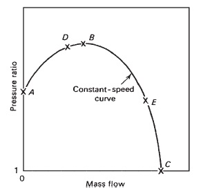
FIGURE 2 Theoretical characteristic.
This point represents the maximum flow obtainable at the articular rotational speed. Other curves can be obtained for different speeds. Figure 3 illustrates the actual variation of pressure ratio over the complete range mass flow and rotational speed. The left-hand extremities of the constant-speed curves are joined up to form what is known as the surge line. The right-hand extremities represent the points where choking occurs.
Since the isentropic p-T relation is given by:

Therefore, the form of the curves of the temperature ratio plotted on the same basis will be similar to the pressure ratio plotted. The isentropic efficiency curves are plotted in Fig. 3. The efficiency varies with the mass flow at a given speed in a similar manner to the pressure ratio. However, the maximum value for all speeds is approximately the same. A curve representing the locus of operating points at maximum efficiency is shown in Fig. 3. Gas turbines are usually designed to operate on this curve.
AXIAL-FLOW COMPRESSORS
The performance of axial-flow compressors exceeds that of the centrifugal compressors. Axial-flow compressors are used in the greater proportion of gas turbines of all applications. This type of compressor is described as “the reversed multistage axial flow turbine.” In axial compressors, the flow is decelerating or diffusing by causing the fluid to pass through a series of expanding passages where the pressure rise is obtained by reduction in velocity. For good performance, the blades of the compressor rotor form series of diverging passages. In the case of a turbine, the passages are converging. Figure 4 illustrates the fundamental differences between the two types. Stalling troubles are prevalent in axial-flow compressors. Stalling occurs when the relevant angle of incidence between the flow direction and the blades becomes excessive. Since the pressure gradient is acting against the direction of the flow, there is always danger to the stability of the flow pattern. Breakdown can easily occur at conditions of mass flow and rotational speed that are different from the ones for which the blades were designed.

FIGURE 3 Centrifugal compressor characteristics. (a) Variation of pressure ratio in a
centrifugal compressor; (b) variation of isentropic efficiency in a centrifugal compressor
The axial-flow compressor has two main components: (1) the rotor and (2) the stator. The rotor carries the moving blades and the stator the stationary rows. The stationary rows convert the kinetic energy imparted to the working fluid by the rotor blades to pressure increase. Also, the stationary rows redirect the flow into an angle that is suitable for entry to the next row of moving blades. Each stage consists of a stationary row followed by a rotating row. A row of inlet guide vanes is usually provided to the stator upstream of the first stage. They direct the flow correctly into the first row of rotating blades. The characteristic curves of an axial-flow compressor are similar to those of a centrifugal compressor. Figure 5 illustrates the axial compressor flow characteristics.

FIGURE 11.4 Comparison of typical forms of turbine and compressor
rotor blades.
Blow off valves are used sometimes to prevent surging when it is expected to occur near the rear of the compressor. Air is discharged from the compressor at some intermediate stage through a valve to reduce the mass flow through the later stages. Figure 6 illustrates the effects of the blow off valve on the compressor characteristics. Figure 7 illustrates the effect of the blow off valve and increased nozzle area on the compressor characteristics. A twin-spool compressor is another technique used to prevent surging by splitting the compressor into two (or more) sections, each being driven by a separate turbine at a different speed.

FIGURE 11.5 Axial-flow compressor characteristics. (a) Variation of pressure ratio in an
axial flow compressor; (b) variation of isentropic efficiency in an axial flow compressor
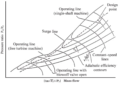
FIGURE 6 Typical gas turbine compressor characteristic. The basis of gas turbine design and engine
governing requirements.

FIGURE 7 Effect of blow-off and increased nozzle area.

FIGURE 8 Transient trajectories on compressor characteristics (two-shaft machine). Acceleration
moves the operating line toward surge. Deceleration moves the operating line away from surge

FIGURE 9 Axial-flow compressor construction. (a) Variable stator vanes; (b) bleed or dump valves.
Inlet guide vanes (VIGVs), variable stator vanes (VSVs), or variable controlled bleed or dump valves (VBVs). All these devices avoid surge. They are illustrated in Fig. 9.
GAS TURBIN COMPRESSORS so on, you can visit other topic :
May you have concern to improve my blog, please comment on below.
Thanks. Hopefully useful.
Thanks. Hopefully useful.


0 comments:
Post a Comment
Terimakasih Buat Sobat Semua Telah Berkunjung Di Blog Ini, Semoga Artikel Dalam Blog Ini Bisa Bermanfaat, Jika Ada Kesalahan Dalam Penulisan Artikel Maupun Kerusakan Dalam Beberapa Link, Mohon Disampaikan Lewat Kotak Komentar.
Atas Kerjasamanya Admin Mengucapkan Terimakasih.
----Demmy Saputra----